
Case study · BUT 2 · 2026
Bluetooth FM Transmitter Test Bench
A LabVIEW bench that tests a Bluetooth FM transmitter: acquisition, digital demodulation and comparison with an analogue radio.

Context
A Bluetooth FM transmitter plugs into a car's cigarette lighter socket. It receives music from a phone over Bluetooth, converts it to an analogue signal, then modulates an FM carrier that the car radio picks up like a station: a very short-range FM micro-station. This second-year BUT GEII project consists in building the bench that tests this type of device.
Goal
Build, in LabVIEW, a functional test bench usable with any transmitter, whatever its brand: capture what it emits, demodulate it digitally, and compare the result with that of an analogue radio.
Working mock-up
- Smartphone: sends audio over Bluetooth (A2DP profile for stereo, HFP for hands-free).
- BT FM transmitter: receives, decodes and converts the audio, then modulates the chosen carrier in the FM band.
- USRP NI 2900: software-defined radio receiver, it acquires the FM signal at the carrier frequency.
- Analogue radio (FM radio kit and loudspeaker): reference analogue demodulation. Any radio will do.
- LabVIEW PC: digital demodulation, display of spectra and time-domain signals, comparison of the two paths.
Approach
- Understand the device: 12 V supply stepped down to 5 V and 3.3 V, 2.4 GHz Bluetooth reception, digital-to-analogue conversion, frequency modulation, reception by the car radio.
- Build the acquisition chain: the USRP NI 2900 is driven by LabVIEW and tuned to the carrier selected on the transmitter.
- Design the interface: a selector dial gives access to five menus: home (device and carrier), received FM signal, FM pilot spectrum, L+R audio signal spectrum, time-domain audio signal.
- Add a reference: the last two menus show side by side the path demodulated by LabVIEW and the one demodulated by the radio.
- Document: hardware, schematics and user guide for the bench.
Bench interface
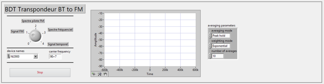
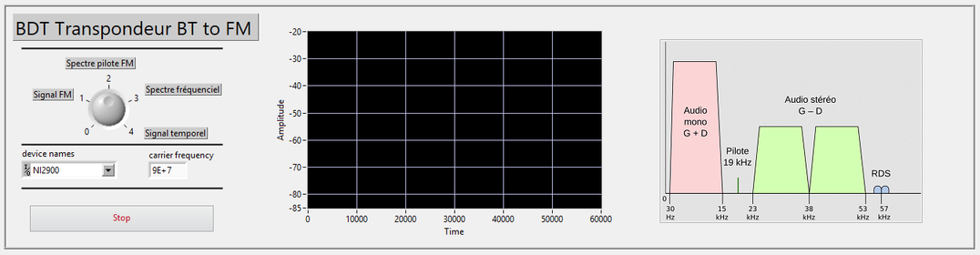
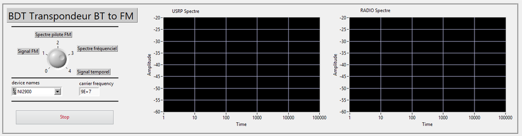
Screenshots taken with no input signal: they show the interface, not a measurement.
Results: what the bench can verify
| Item checked | Method on the bench |
|---|---|
| FM band | Set the carrier to the extremes and check that the emission stays between 87.5 and 108 MHz. |
| Carrier frequency | Check that the device transmits on the chosen frequency, measure the drift and compare it with the manufacturer's tolerance. |
| FM range | Move the transmitter away until the signal is lost (the manual states 6 m). |
| Audio band | Sweep from 1 to 15 kHz while following the spectrum. |
| Noise floor | Measure the time-domain signal with no audio to estimate the signal-to-noise ratio. |
| Bluetooth | Test the A2DP and HFP profiles with iOS, Android, Windows and Linux, the range (class 2, about 10 m) and robustness in the presence of Wi-Fi. |
Limitations
- Audio quality remains limited by FM itself: bandwidth of about 15 kHz, neighbouring stations, electromagnetic interference.
- The reference path depends on the radio used.
- The transmitter's manual gives no signal-to-noise ratio: the bench measures it, but there is no manufacturer threshold to compare against.
- Range tests are manual.